
Storebu will eventually get a tidy 12 V system where most of the daily power use can run directly off the battery bank. The idea is to keep the system fairly simple: solar and charging are gathered at the batteries, while lights and other equipment get their own circuits inside the cabin.
This article shows how I plan to build up the system, from the battery box through to the distribution inside the cabin.
The system is still under construction. Some components haven’t been chosen yet, and certain cable sizes and fuse ratings still need to be checked before I settle on the final solution. The diagram in the article is therefore a planning diagram, not a finished as-built drawing.
Why 12 V?
I want to use 12 V directly wherever it makes sense.
LED lighting, a fridge, ventilation, a camera and many other small loads can run without going through 230 V. That also means I avoid running an inverter continuously just to supply equipment that could run straight off the battery bank in the first place.
The larger heat demands aren’t taken from the batteries either. Cooking and water heating are planned on gas. Heating is done primarily with wood, supplemented by a Wallas or Safire diesel heater.
That doesn’t mean the cabin will be completely without 230 V. An inverter or a separate power station can be used when there’s an actual need for it, but I don’t want to build the whole power system around an inverter.
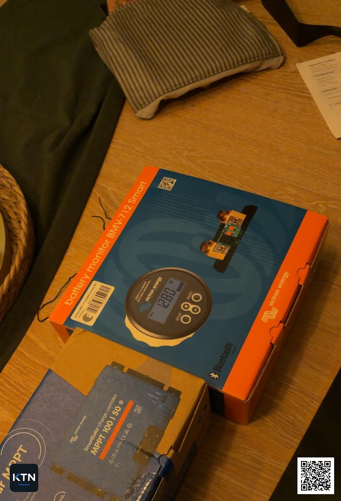
How I’ve split up the system
I’ve chosen to split the system into two main parts.
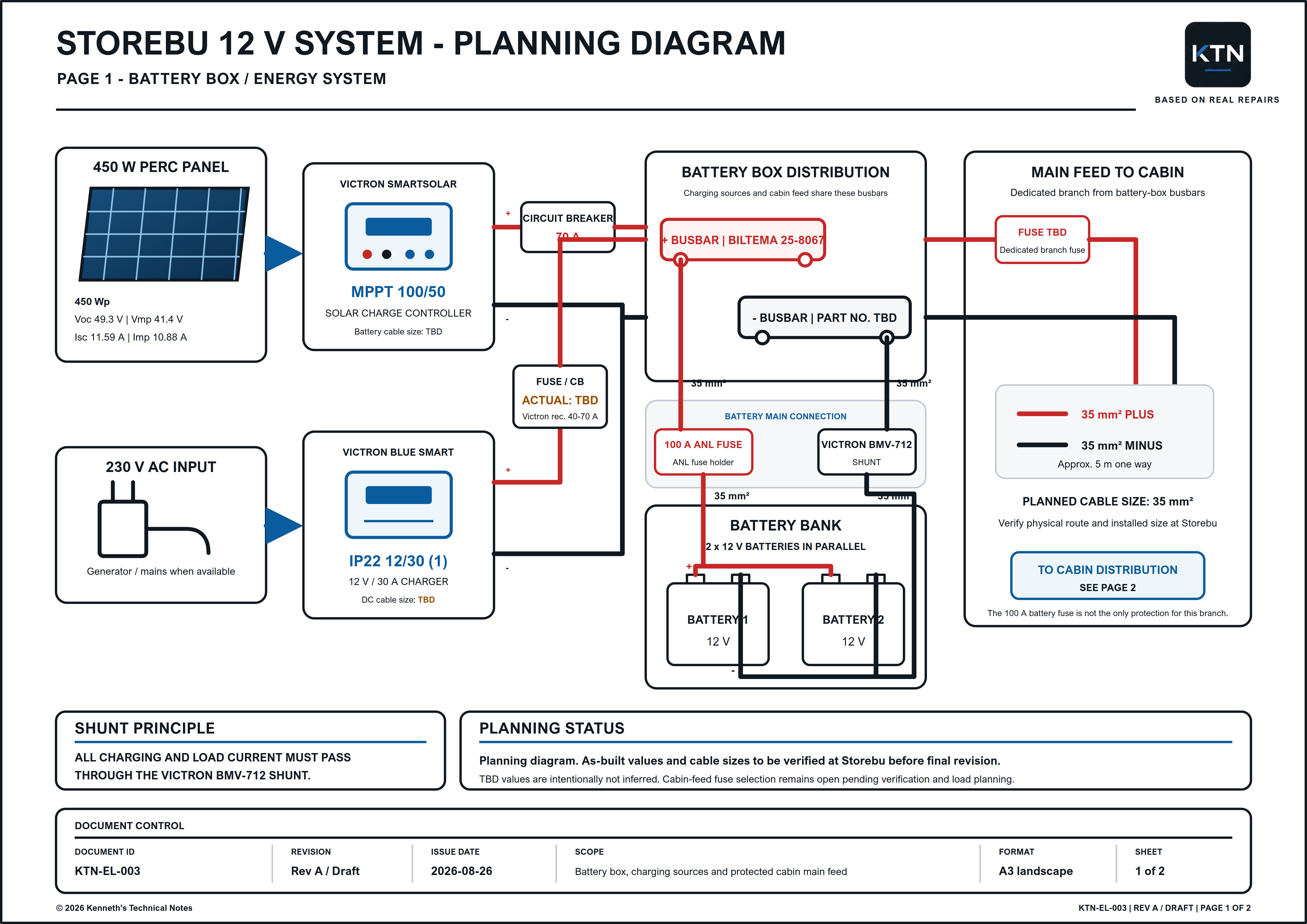
The battery bank, solar charging, main fuse, shunt and busbars are gathered in the battery box. From there, a separate main connection runs into the cabin.
Inside the cabin comes the main switch and a dedicated Blue Sea fuse panel with separate circuits for lighting and equipment.
That makes the system easier to keep track of, while letting me hide most of the wiring inside the interior. I want the electrical system to be accessible when I need to work on it, but otherwise as unobtrusive as possible.
The battery box and power system
The battery bank consists of two 12 V batteries connected in parallel.
Inside the battery box itself I use 35 mm² main cables. On the positive side, the battery bank first passes through a 100 A ANL main fuse before the positive busbar.
On the negative side, the connection runs through the shunt for the Victron BMV-712 and then on to the negative busbar.
It’s important that both charging and loads are connected on the correct side of the shunt. If a negative connection is made directly to the battery, the BMV-712 won’t register that current, and the battery bank reading will be wrong.
The solar setup consists of a 450 W PERC panel and a Victron SmartSolar MPPT 100/50. On the positive side between the MPPT and the battery system I use a 70 A breaker.
The solar panel is meant to do most of the charging during the lighter part of the year. On Senja, a large solar panel doesn’t help much in the middle of the polar night, so I also want the option of charging the battery bank from a generator or another available 230 V supply.
For that I have a Victron Blue Smart IP22 12/30, which can deliver up to 30 A.
The fuse and cable size on the DC side of this charger haven’t been decided yet. I’ll settle that according to Victron’s specifications and the actual cable routing once the charger is installed.
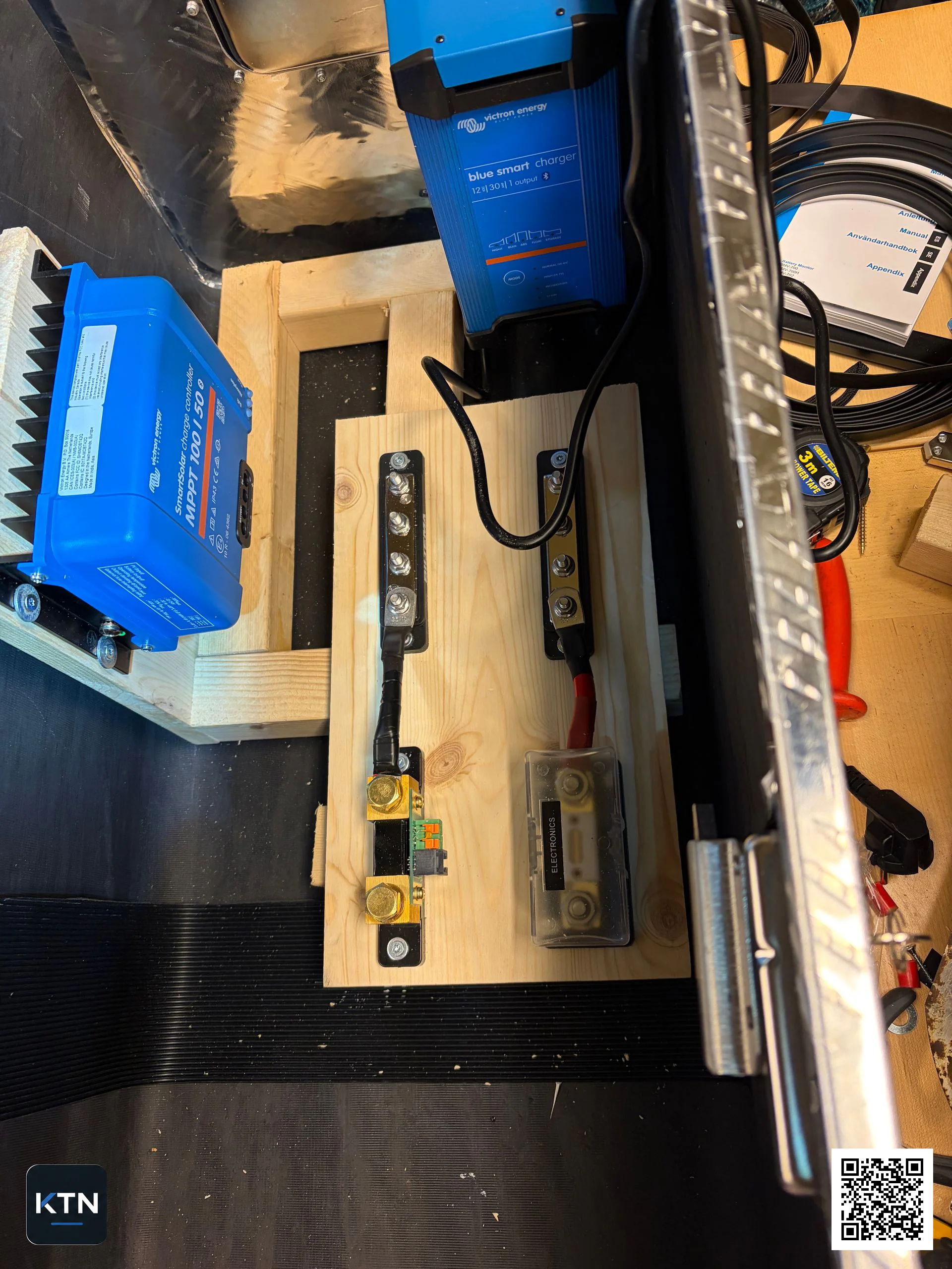
From the busbars, a separate main connection of about five metres is planned to the cabin.
The starting point is 35 mm² on both positive and negative. Before I lock in this size, I want to check the actual cable route at Storebu. That assessment is easier once I know exactly where the cable can be routed and how long the connection actually ends up being.
The positive cable to the cabin will also get its own fuse at the battery system. The value hasn’t been set yet.
I don’t want to base the protection of this cable solely on the battery bank’s 100 A main fuse. The main connection to the cabin needs to be sized and fused as the circuit it actually is.
You can use KTN’s 12 V DC voltage drop calculator to assess the voltage drop in the main cable.
Distribution inside the cabin
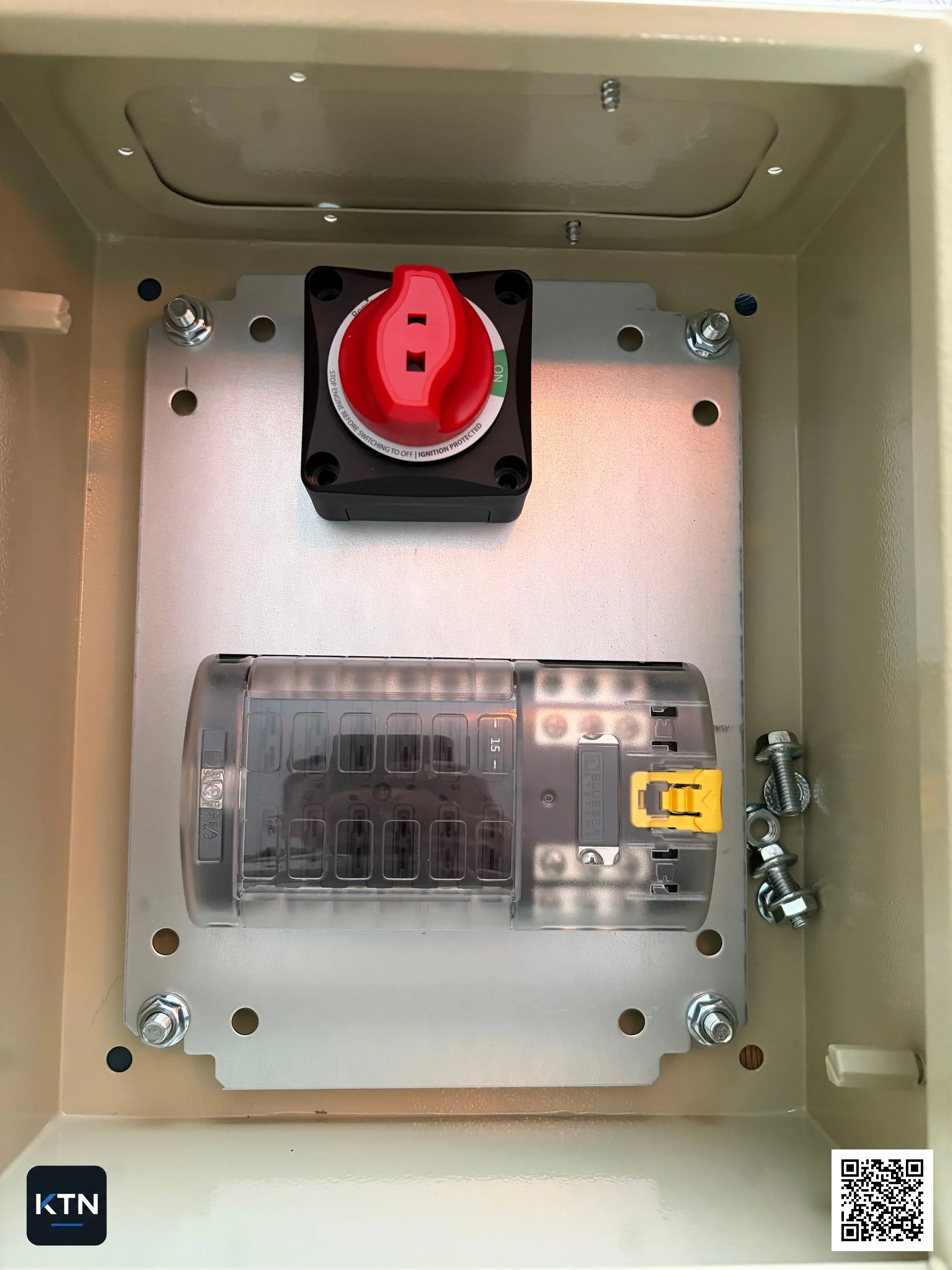
When the main cable enters the cabin, the positive side first passes through a Victron Battery Switch On/Off 275 A.
I wanted a physical main switch that makes it easy to disconnect the whole cabin distribution. That’s useful both when the cabin is unused and later when I need to work on the system.
From the main switch, power continues to a Blue Sea BS 5026 fuse panel. The negative cable goes to the integrated negative bus in the same panel.
The panel has twelve fuse positions, and the plan currently looks like this:
- Wallas/Safire heater – model not chosen, planned at 6 mm².
- 12 V kitchen extractor fan.
- 12 V fridge – model not chosen.
- Bathroom, Cinderella auxiliary functions and lighting.
- Lighting north – 2.5 mm².
- Lighting south – 2.5 mm².
- Facade lighting and possibly a camera.
- Dedicated 12 V charging for an EcoFlow DELTA 2 – 6 mm².
- Lighting in the storage room – future circuit.
- Heavy-duty circuit or EcoFlow charging in the storage room – future 6 mm² circuit.
- Spare position.
- Spare position.
This is a plan, not a finished circuit list. Fuse values will be set once the equipment and cable sizes for each circuit are known.
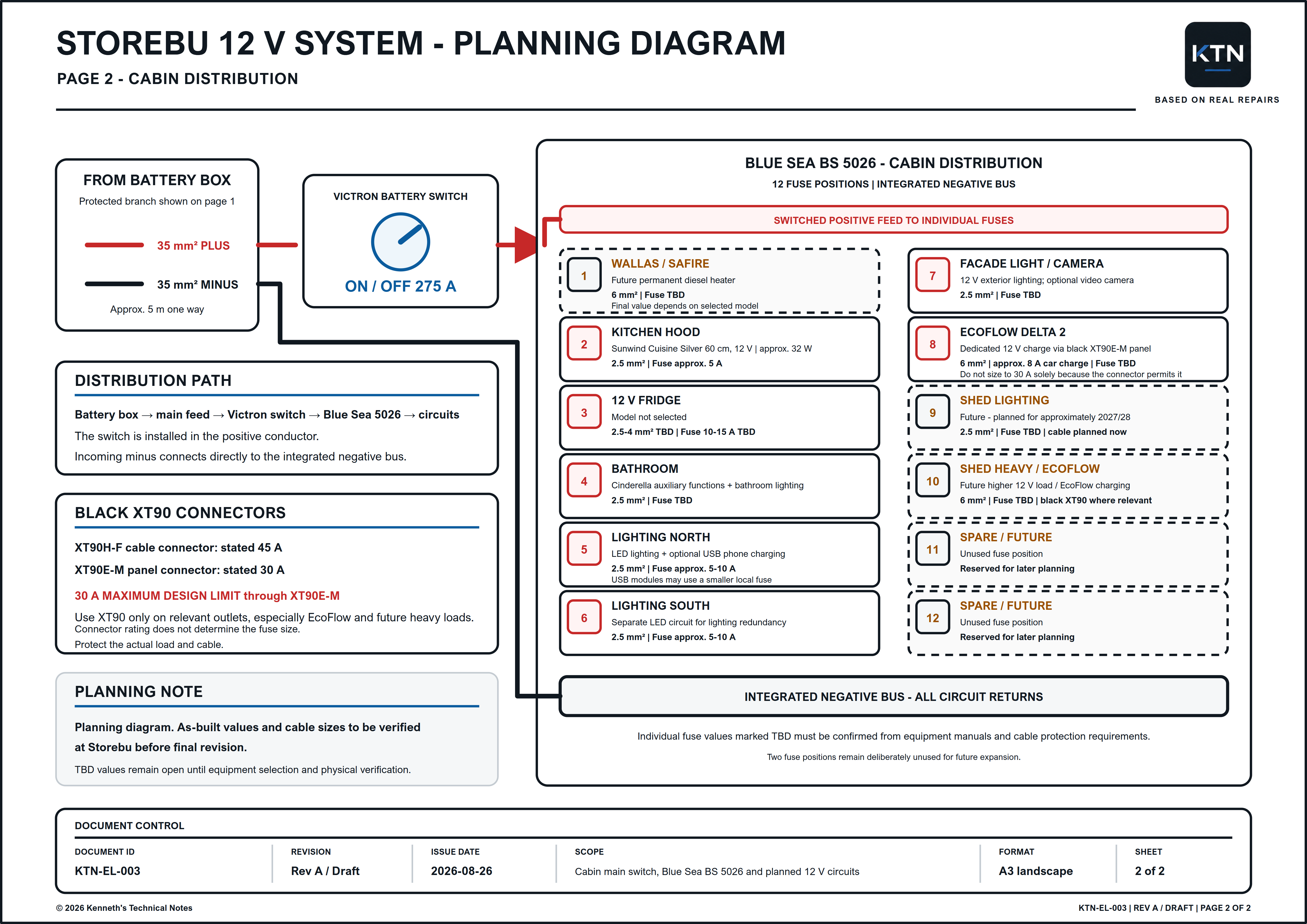
Open the full two-page planning diagram as a PDF
I’ve deliberately split the lighting into a north and a south circuit. It costs little to do that while the system is being built, and I like the idea that the whole cabin won’t go dark if one lighting circuit develops a fault.
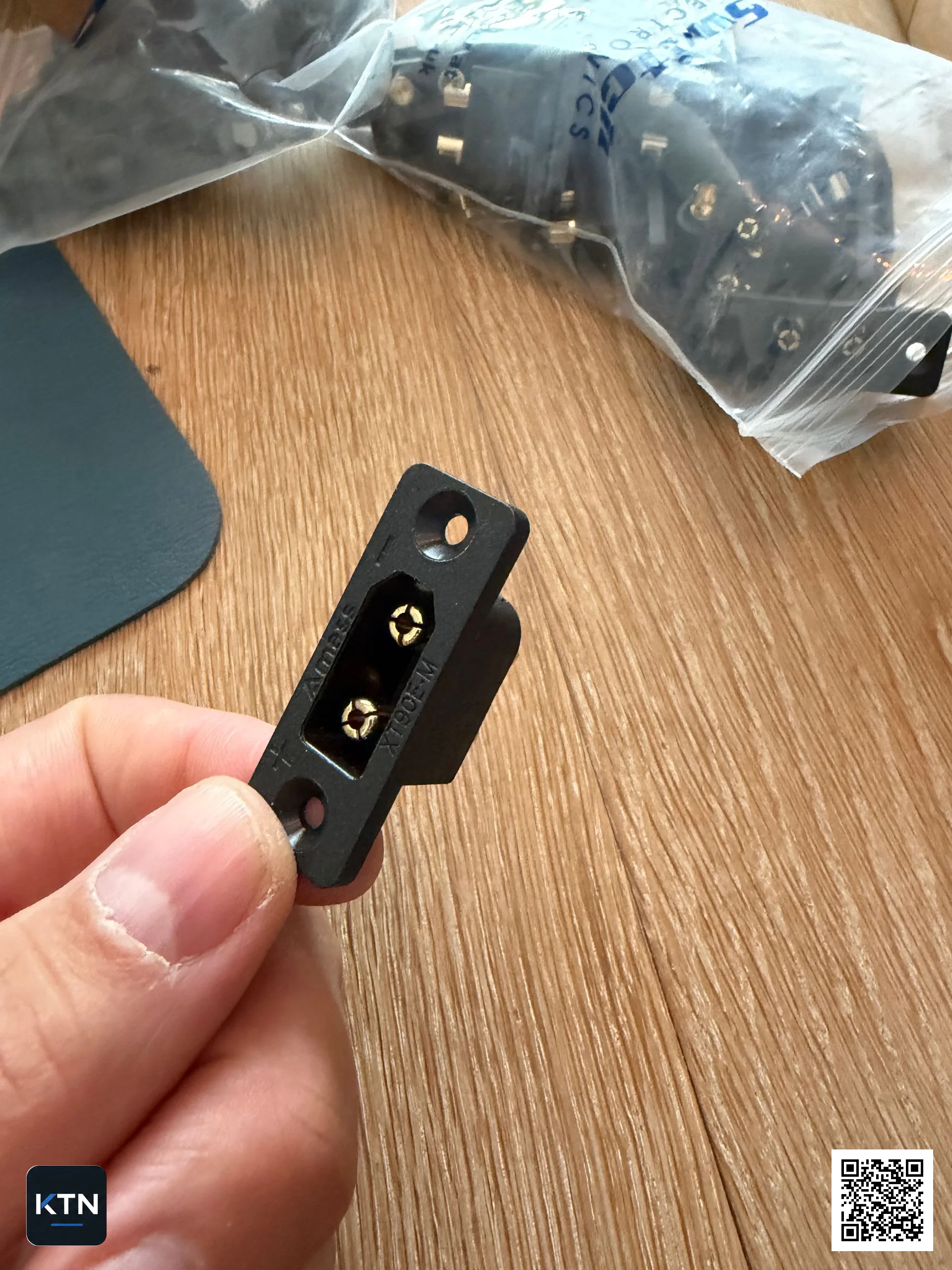
XT90 as a 12 V outlet
For some of the higher-power 12 V outlets I’ve chosen black XT90 panel connectors.
I considered a more traditional outlet solution, but wanted something that could be built in fairly discreetly. XT90 is compact, mates well, and suits things like the planned 12 V charging of the EcoFlow DELTA 2.
The same solution may also end up being used for other higher-power 12 V loads later on.
That said, the cable isn’t the only thing that determines how much current such a circuit can be fused for. The panel connector is part of the current path and has to be included in the sizing. The fuse should therefore be matched to the cable, the connector and the load that’s actually going to be connected.
The distribution box is built up around the Victron main switch and the Blue Sea panel. At the same time, I try to place the components so that fuses and connections stay easy to reach once everything around them is finished.
What I still need to settle before the system is finished
There are still a few things I’ve deliberately left open:
- The cable route between the battery box and the cabin needs to be measured and checked before the 35 mm² size is finalised.
- Several fuse values and some cable sizes haven’t been set yet.
- The model for the 12 V fridge hasn’t been chosen.
- I also haven’t decided which Wallas or Safire heater I’ll end up using.
- The circuits to the storage room are entered as future circuits and probably won’t happen before 2027/28.
- The Sunster TB10PRO is used as a separate, temporary solution and isn’t drawn in as part of the main system.
I’d rather leave these points open than fill in cable or fuse values in the diagram just to make the drawing look “finished.” They can be decided once the components are chosen and I’ve checked the installation physically.
What’s next
The basic principle for Storebu is now settled: batteries, charging and power monitoring are gathered in the battery box, while the cabin gets its own main switch and fuse distribution.
Most of the daily load should be able to run directly on 12 V, while 230 V becomes something I use when there’s an actual need for it.
The next step is to check the cable route between the battery box and the cabin and get the remaining component choices in place. As the system gets finished, the planning diagram can be replaced by an as-built version showing how the system actually ended up.
I’ll come back then with photos of the finished installation.